Most of us working in software development have probably heard of Quantum Computers and Qubits, you may or may not currently have some understanding of what they are, but did you know you can play around with some real Qubits, running on actual Quantum Computers, online, for free?
This was news to me when I first heard it! and it sounded like a fun side project, so I decided to give it a go. Unfortunately much of the literature online surrounding quantum computing is either very high level and has no useful information about how to actually write a program for a Quantum Computer, or it is super low level quantum physics and complicated maths involving lots of Greek letters which the authors of the articles rarely bother to explain.
I might have to write an article that simplifies, or at least tried to explain, the basics of writing a program once I’ve got my head around it but in the mean time here is a brief summary of the basic concepts:
Most Quantum Computers use either electron spin (spin up or spin down) or photon polarisation (horizontal or vertical) to create their Qubits. The 2 possible states give you your 1 and 0 boolean values that we’re familiar with from classical computing, however in quantum computing there is a third state which is a superposition of both 1 and 0. Most Quantum Computers seem to use electrons so that’s what I’ll focus on in the rest of this article.
At the moment Quantum Computers contain a very small number of Qubits and (read 1-10) with the biggest Quantum Computers having something in the region of 120+ Qubits. As such we’re still very much at the level of performing basic operations on individual Qubits, something similar to assembly code but it’s often represented as a circuit. Here is the very first Quantum Circuit that I created, it’s a very simple random number generator:
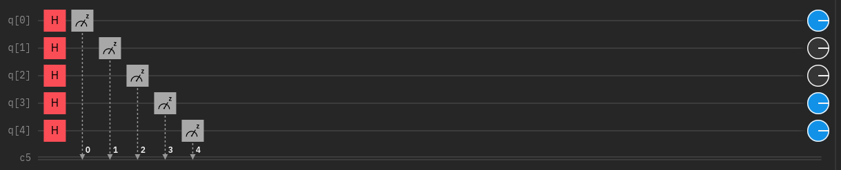
This is actually an excellent use case for a Quantum Computer since classical computers only generate pseudo random numbers, where as Quantum Computer can give us genuinely random numbers. This could be useful in scientific applications or perhaps cryptography both of which could make use of genuinely random numbers.
In the diagram above, each horizontal line is a Qubit, anything you place on the line is an operation you want to perform on the Qubit, usually these operations are some sort of rotation along the X, Y or Z axis or a measurement, however you can also do other things like entangling Qubits. The blue and grey circles on the the far right of the diagram are just one possible simulated output (11001 in binary).
Here I have used the “Hadamard” transformation (the red H blocks) which, regardless of input, essentially gives you a 50/50 chance of getting a 1 or a 0. That is actually an over simplification because if you do a second Hadamard transformation on the same Qubit it will flip the value back to it’s original state i.e. a 1 put through two Hadamard transformations in a row will produce a 1, likewise a 0 put through two Hadamard transformations will produce a 0. I found this video very helpful in explaining some of the basics, especially the Hadamard gate:
Continuing with the basic circuit I created, the grey blocks with the z in the corner are the measurement blocks, at this point the superposition of each Qubit is destroyed as it gets measured. This isn’t actually an issue in this circuit as we only perform the one transformation and then get output.
Here is an image of the full editor (the IBM Quantum Composer). Top left is the full list of blocks that are available to you, it would be nice if they added hover over text with the name of the transformations rather than just presuming you know what H, T, S, Z, and P etc all stand for. Bottom left is a simulated run that gives you a rough idea of what to expect as output, this has some randomness built in which is based on the customisable “Virtualization seed” (see top right).
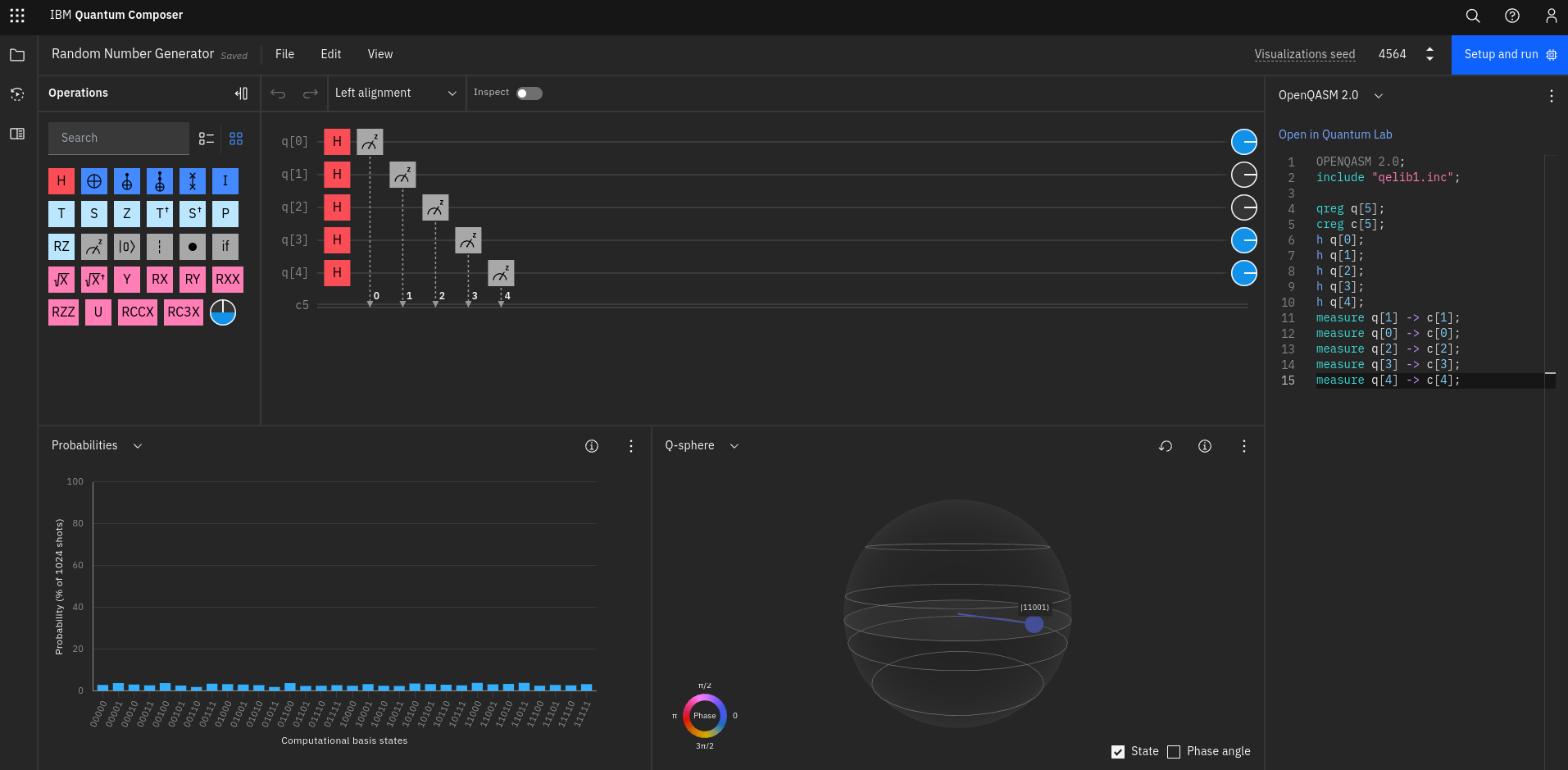
You can see that you also get some code that is equivalent to your circuit on the right and a Q-Sphere at the bottom which is not to be confused with the similar looking Bloch sphere. The Bloch sphere is a common way of representing the state of a single Qubit and visualising the effects different transformations will have. The Q-Sphere is an IBM specific representation of multiple Qubits and I only have a very basic understanding of what it’s representing but if all Qubits were 0 it would point to the top and if all Qubits were 1 if would point to the bottom, I believe longitude has something to do with the “phase” but don’t ask me to explain that in any more detail just yet.
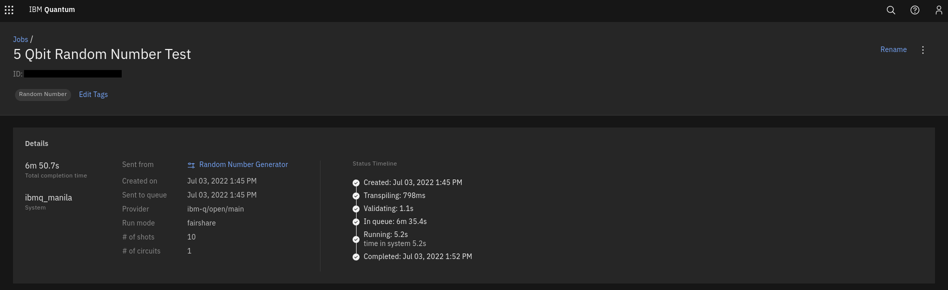
When you go to actually run your program you will be given several different servers to choose from, some only do simulations, others are actual Quantum Computers, so be careful which you choose. Once you’ve selected an actual Quantum Computer you’ll be placed in a queue and your code will run as soon as it reaches the front. In my case I was given an estimate of several hours before I reached the front of the queue but then the code was run about 5 minutes later so the estimate isn’t super reliable. Here is are the details of my test run and my actual results:
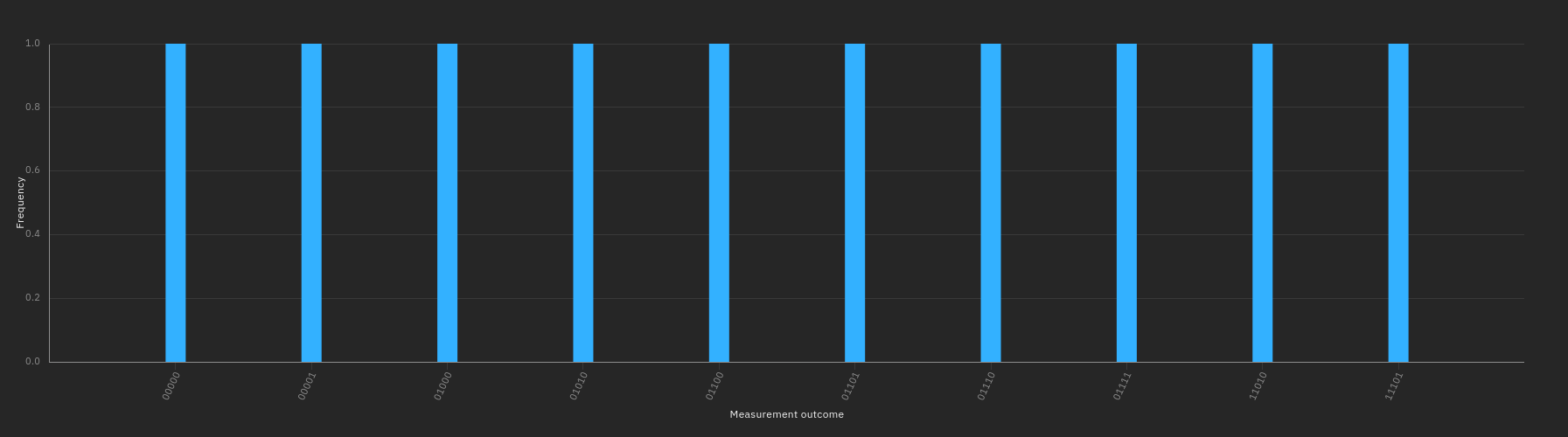
I only did 10 “shots” or “runs” in English, you might find the results somewhat underwhelming but these are genuinely random numbers from a real quantum computer, I think that’s interesting. If you want to try if for yourself check out IBM Quantum, alternatively if you’d just like to have a quick play around you can try the Quantum JavaScript library which has a nice drag and drop simulator on the homepage.
0 Comments